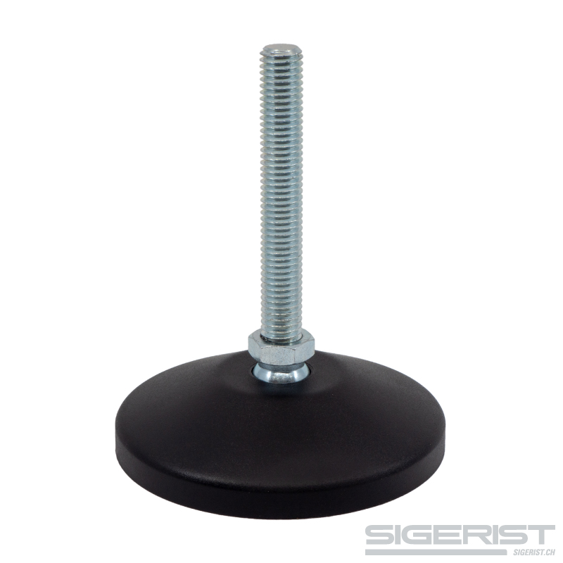


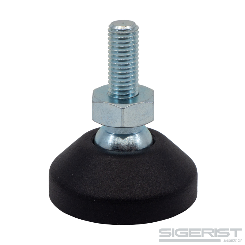
Leveling foot galvanized steel diameter 60 mm – hinged foot
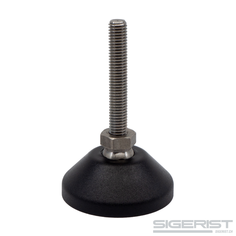
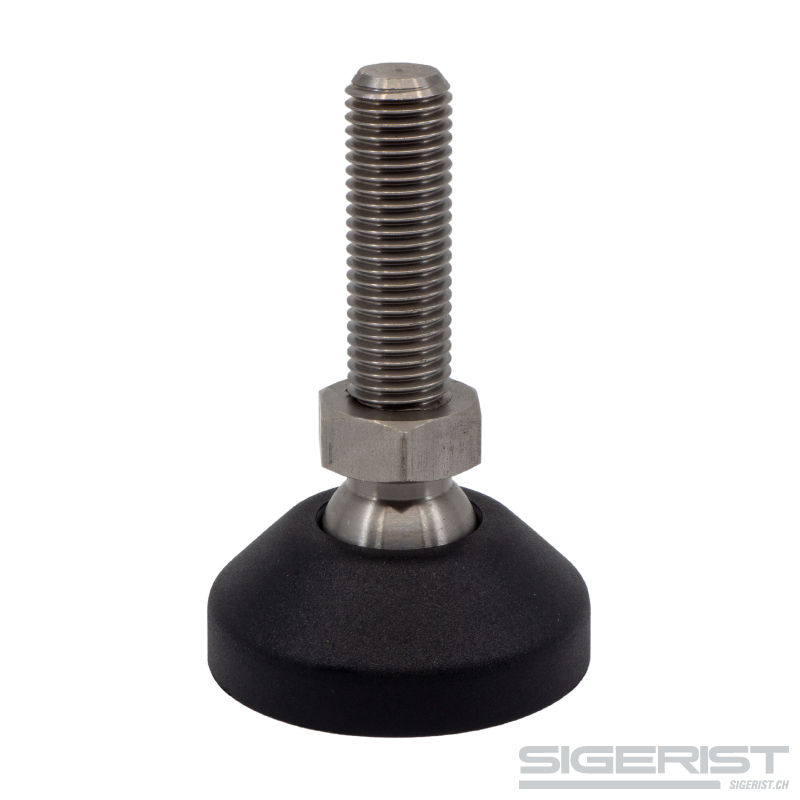
The leveling foot is made of galvanized steel with a diameter of 60 mm. The articulated foot is designed for loads of up to 500 kg per foot. It consists of a threaded rod with ball joint and can therefore adapt well to uneven ground.
- Description
- Properties
- more detailed information
- Contact & Inquiries
Description
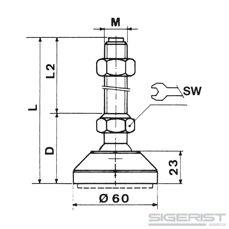
The leveling foot galvanized steel diameter 60 mm – hinged foot is available in the versions listed below.
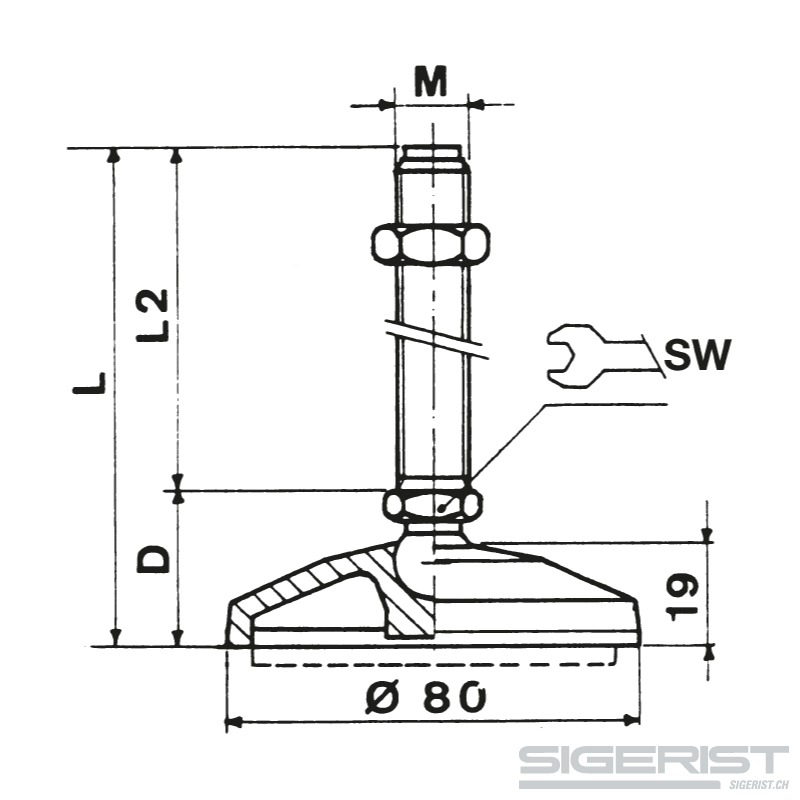
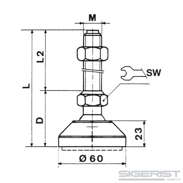
| Type | Thread x L2 | D | Length L | SW | Bolt Type | |
|---|---|---|---|---|---|---|
| mm | mm | mm | kg | |||
| S60M12x50S | M12 x 50 | 42 | 92 | 24 | 2 | 1500 |
| S60M12x100S | M12 x 100 | 42 | 142 | 24 | 2 | 1500 |
| S60M12x150S | M12 x 150 | 42 | 192 | 24 | 2 | 1500 |
| S60M16x50S | M16 x 50 | 42 | 92 | 24 | 2 | 1500 |
| S60M16x100S | M16 x 100 | 42 | 142 | 24 | 2 | 1500 |
| S60M16x150S | M16 x 150 | 42 | 192 | 24 | 2 | 1500 |
| S60M20x100S | M20 x 100 | 42 | 142 | 24 | 2 | 1500 |
| S60M20x150S | M20 x 150 | 42 | 192 | 24 | 2 | 1500 |
| S60M20x200S | M20 x 200 | 42 | 242 | 24 | 2 | 1500 |
You will find an overview of all machine feet here.
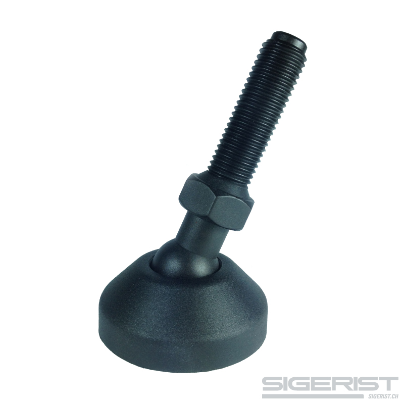
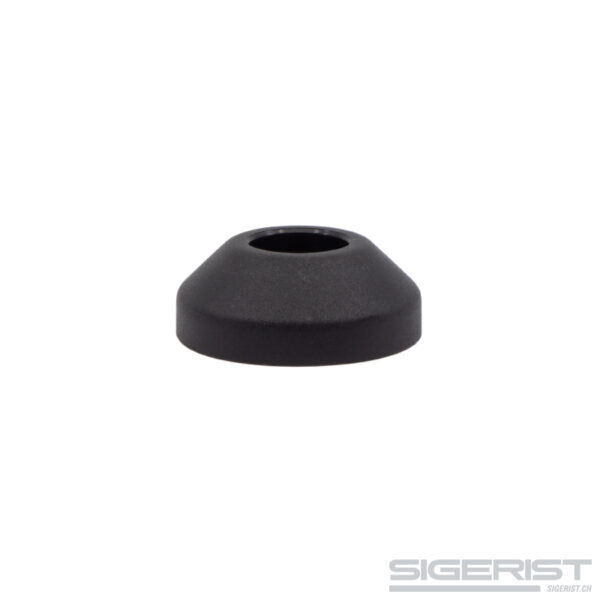
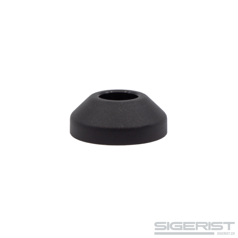
Foot plate
- reinforced polyamide
- black
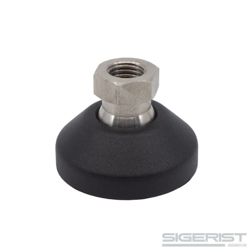
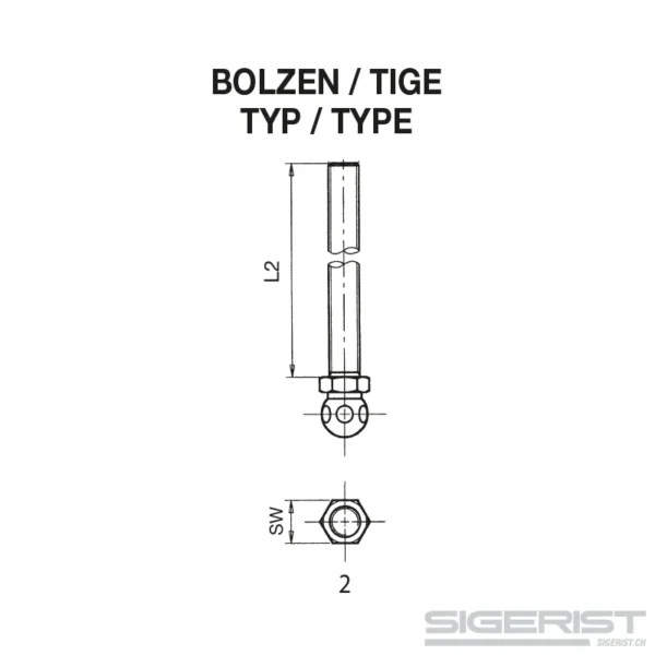
Threaded rod with ball joint
galvanized steel
Leveling foot
Application of leveling feet and their structure
To enable exact alignment, adjustable machine feet are used to set up machines or systems. This can refer to a height compensation to other devices or also to the compensation of unevenness and inclined installation surfaces. With the latter, the leveling foot is the only way to achieve a stable stand with exact levelling.
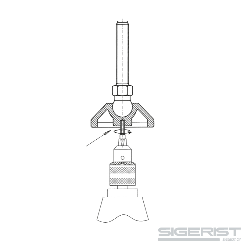
The leveling foot consists of two basic elements. The foot itself usually has a disc shape, but can also be designed differently for special designs. Thus an eccentric fastening can be selected, whereby the foot consists of solid plastic. With all leveling feet a threaded rod is placed vertically, which is provided at the end with a ball head and finds in a ball socket in the foot stop. This allows the threaded rod to be inclined in all directions.
Components and material
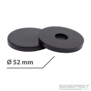
In addition to the main components, other elements are used which, however, can differ considerably depending on the intended use. The threaded rod on all machine feet is equipped with a nut, which makes height adjustment in the hundredth of a millimetre range possible in the first place. The machine or worktable rests on this nut and is secured with a locknut. Anti-slip soles are used for free-standing tables and machines, which can be used optionally for each machine foot. They are made of oil- and grease-resistant nitrile rubber.
The feet themselves are made of black polyamide, whereby the steel ball socket for the ball joint has also been cast in. The threaded rods are available in galvanized steel (FE.ZN), stainless steel (INOX 1.4305) or some types also have a polyamide screw with integrated steel insert (PA.FE).
Mounting, dimensions and load capacity
The leveling foot sizes start with a diameter of 40 millimeters. A size that is best suited for lower loads such as a worktable or shelving and conveyor systems. But even the smallest of the leveling feet has a load capacity of 500 kg per foot. The largest available diameter is 123 millimetres, with a maximum load of 3500 kg per foot. In between are plate diameters of 50, 60, 80, 100 and 110 millimetres, with the load capacity increasing with increasing diameter. From a diameter of 80 millimetres, the leveling feet are also available with floor mounting.
Each joint foot size is offered with different threaded rods in diameter and length. Threads are available in sizes M8 to M24 and a threaded rod length from 50 to 200 mm.
Correct choice and mounting
Special attention must be paid to the expected load. This includes the dead weight of the machine to be fixed and also the weights of the workpieces or materials to be processed. One-sided loads can also occur, because machines do not have the same weight at all corners.
An leveling foot with a low load is sufficiently secure with the aid of anti-slip soles. If, on the other hand, strong vibrations and shocks are to be expected as a result of work processes, bolted machine feet prove to be more advantageous or even necessary. To do this, the machine holes must first be transferred to the ground in order to anchor each individual machine foot precisely.
After the machine or worktable has been placed on the threaded rods, levelling is carried out with the lower nuts. In case of unevenness or ground inclination, the threaded rods are automatically vertically positioned by the ball joints. The locknuts are then screwed on and tightened.